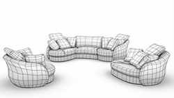
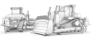
Polygonal modeling is the first type of three-dimensional modeling that appeared in those days, when the X, Y and Z-axes coordinates had to be manually entered from the keyboard to define the position of points in a three-dimensional space.
As we know, when three or more coordinate points are defined as vertices and connected by edges, they form a polygon, which can be assigned a certain color and a texture. Connection of such polygons can simulate almost any object.
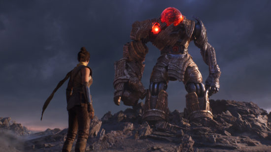
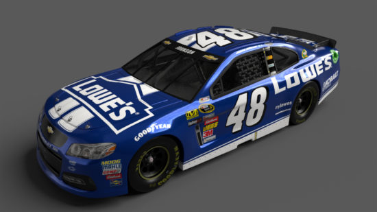
This type of 3D modeling is the most common form of 3D models. Furthermore, polygonal 3D models are widely used in feature films industry as well as in video games production.
The main disadvantage of polygonal modeling is that all objects are composed of tiny flat surfaces and polygons should be very small, otherwise the edges of the object will look faceted. This means that if the object in the scene is expected to be increased, it is necessary to create hundreds or even thousands of polygons (the object will then be of high resolution) even though most of them will be redundant when distancing the object.
As a 3D modeling company, we offer only premium-quality assets for all product types, whether you deal with video games or other three-dimensional visuals. Our artists wield the most advanced tools to create 3D environments, props, and characters for your business.
In this article we’ll pay some attention to techniques of polygonal 3D modeling, which can greatly improve on the appearance of a 3D model.
The next two popular techniques of polygonal modeling refer to a box modeling method:
Extrusion
 Almost all 3D modeling software programs contain extruder tool in a basic package. This simple tool is one of the first the modelers use to start shaping a model. It is applied to a face (or a set of faces) and creates new faces of the same size and shape connected to all existing edges by a face. Simple example of extrusion is creation of a cube connected to the surface at the location of the face from a square.
There are two ways to manipulate a mash through extrusion. You can either collapse a face in itself or to extrude it outwards.
One can extrude either a simple geometric shape, like cube or pyramid, or edges of a model. To help you understand the principals of extrusion, let’s look at the following examples:
- Extrusion of a pyramid. A modeler can transform a primitive pyramid with a 4-edged base into a complex shape by extruding the pyramid base downward in the negative Y direction. As a result the modeler creates four new vertical faces between the base and the cap of a model. Good examples of extrusion of a pyramid can be found in a house or table legs modeling.
- Extrusion of edges. It is important to duplicate the edge to further pull it or rotate in any direction together with a new automatically created polygonal face, which connects the two edges. Extrusion of edges is primary used in the contour modeling.
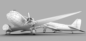
Subdivision
 3D artists of all times work for creation of smooth surfaces of 3D models. Typically polygonal modeling begins with primitive geometric shapes (like cube or triangle) of low resolution consisting of a very small number of faces. This technique presupposes the division of each face into smaller faces (usually into four faces). Subdivision technique helps to add higher resolution to a 3D model. In other words, it is practically impossible to create a finished model without the smallest subdivision level.
Subdivision can be applied either uniformly or selectively to a 3D model.
A uniform subdivision divides the whole surface of a 3D model. Uniform subdivisions are reasonable to use on a linear scale, which means that each polygonal face will be divided into four faces. This type of subdivision allows to smoothen the edges on the surface of a model.
Selective subdivision can be applied to some parts of the modeled surface. This type of subdivision presupposes the placing of the additional edge loops. This loop can be added to any set of faces, leaving the rest of the meshes unchanged. Selective subdivision is generally applied to elements which require high resolution and high detailization, such as eyes, lips, etc.
One more way to refine the model surface without adding too much smoothness to it is to combine both subdivision methods. One can use edge loops to prepare a surface before using the uniform subdivision. If the modeler wants to leave some edges sharp, he can place an edge loop on one side of the edge before uniform subdivision.
In spite of the fact, that subdivision method is in demand, some experienced 3D artists manage to model smooth 3D surfaces without subdividing the faces of a model.
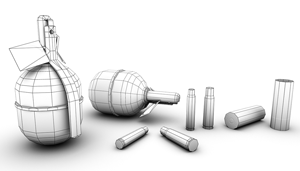
Bevels or Chamfers
 Initially the edges of a 3D model are sharp and the model definitely does not have a natural look. Almost every object in the real world possesses some level of edge roundness (if it has any edges at all).
So what is bevel and chamfer? And how does it affect the smoothness of a 3d model surface?
Normally, every edge on a polygon occurs at 90 degree between two polygonal faces. A beveled edge is not perpendicular to the faces of a polygon. When you bevel the edges between polygonal faces you create a face at a 45 degree angle (or other degree angles) between these planes to round the corners of a model and make it look more convincing. The modeler can define the length and roundness of a bevel himself.
The words “chamfer” and “bevel” often overlay in meaning and it is sometimes difficult to differentiate between them, as both of them are used to achieve the same goal, to soften the edges of a model. But there are still some differences between these issues:
A bevel usually extends from one face to another, while a chamfer extends only partway to the far face.
A bevel meets another surface or line at any angle but 90 degrees. A chamfer is a beveled edge that connects two lines. If the surfaces are at 90 degree angles, the chamfer will typically be symmetrical at 45 degrees.
Refining
 In simple words, refining is the ability to correct shapes.
A modeler starts shaping a model with simple techniques like extraction and subdivision, but as a result he gets only a rough model with sharp edges. The first stages can take a modeler only half a minute, but he can spend hours on refinement (or shaping) of a model surface, especially if the model requires high level of details, as it is a very delicate and time-consuming procedure.
Refining can be defined as pushing and pulling vertex as the modeler manually changes the x,y or z axis of a model to smoothen the surface of a detail.
As a rule, refinement can be used at any stage of modeling and complements all basic techniques, whether it is extrusion, subdivision or beveling. To sum up, a refinement technique is undeniably an essential part of creation of a realistic 3D model.
Future Belongs to Splines?
Due to technological progress and higher power of processors and graphics cards, 3D computer graphics software often choose splines as a method of 3D modeling. At the moment there is already 3D computer graphics software which does not support polygonal modeling. However, thanks to the immense popularity of real-time 3D games, polygonal modeling earned its fame. Nowadays multi-functional tools for editing of polygons are gradually transformed into tools for working with splines.